Mods:
- True bypass using the original switch (first picture), no money needed.
- Sweep range caps (try out values like 8n2F and 15nF - see the red circle in the second picture - they are selectable to be in parallel with a 10nF cap by the tri-wah switch).
- Guitar cable inner wire in the bypass path (input jack - switch - output jack), use a good guitar cable part to keep the original input tone (I like the 0.5 mm cables).
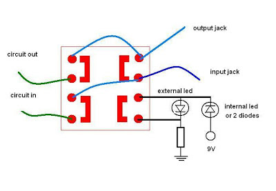
True bypass adaptation schematic:
Bypass wire (black thick wire):
* Change the jumpers in the circuit board to make the necessary connections.
** The GCB-95 schematic is quite similar.


Hello!
ReplyDeleteDo you know what is the input resistor?
r5 or R7?
I've identified a 5M6 resistor in parallel to the input jack and a input capacitor in series to this jack, after this capacitor a high value resistor to the ground and the base of the first transistor. Thanks.
ReplyDeleteI have a rocktron classic wah, will this mod work for mine? coz the circuit seems similar. If yes, do i have to give 9v only to switch?, what do you mean by circuit input and circuit output, where do i take the connection. Pl clarify me on that. Also pl explain the working of the foot switch i.e pin outs and etc
ReplyDeleteThanks,
Arun.
Hi, I dont know the classic rocktron, so i can't say... sorry. The foot switch in the picture here, works like that: when the right side is on, the left side is off, and when the left side is on, the right side is off.
DeleteThe circuit in is the begning of the active wha circuit and the circuit out is the output of the wha circuit. The true bypass switch isolates the active circuit when the effect is off, so as not make any interference in the guita signal.
DeleteHi there,
ReplyDeleteI have a rocktron classic wah and the circuit seems to be similar to tri wah, will the bypass mod work?? If yes, first, 9v supply is given to internal LED or diode as you mentioned has to be given directly? and 2 diodes should me in series or parallel at supply? second, where is the input and output in the circuit and how should I find them?
Pl request you to clarify me on the above mentioned queries. Expecting your reply as soon as possible.
Thanks,
Arun.
Hi, I dont know the classic rocktron, so I can't say... I m sorry. The foot switch in the picture here, works like that: when the right side is on, the left side is off, and when the left side is on, the right side is off.
DeleteThe led trick is used to turn the external light off, because I didnt have a lot of options on this switch, when the switch on the right side is on, the led is in a short circuit and the light is off. The internal led or diodes are limiting the current to the original product max value.
Sorry for the delay in reply.... tks...
Hello, I know this thread is old, but after trying to understand what was happening in the photos and following the schematic, I finally managed to modify the Classic Wah. It's exactly the same circuit in every aspect except for the external potentiometer. Even the wire colors are the same. Here are my conclusions: the black wire going towards the output isn't necessary to use; you should leave the gray one connected as it is from the factory (no signal is lost). Then, the external LED needs to be desoldered because it's connected the wrong way around. Lastly, the trick with the internal LED that guitar4geek uses in the photo is enclosed within heat shrink tubing. It took me a while to figure that out! Other than that, thank you very much guitar4geek for the mod, it's the only thing I found on the internet to avoid using a 3PDT switch.
ReplyDeleteHello, I know this thread is old, but after trying to understand what was happening in the photos and following the schematic, I finally managed to modify the Classic Wah. It's exactly the same circuit in every aspect except for the external potentiometer. Even the wire colors are the same. Here are my conclusions: the black wire going towards the output isn't necessary to use; you should leave the gray one connected as it is from the factory (no signal is lost). Then, the external LED needs to be desoldered because it's connected the wrong way around. Lastly, the trick with the internal LED that guitar4geek uses in the photo is enclosed within heat shrink tubing. It took me a while to figure that out! Other than that, thank you very much guitar4geek for the mod, it's the only thing I found on the internet to avoid using a 3PDT switch.
ReplyDeleteTks, in this mod I have (1) moded the Tri-wah original switch configuration to make a true bypass, it wasn't a true bypass. (2) I have played with the sweep range capacitors to make on my taste and (3) change the signal path wires to a guitar cable wire (0,5 mm), to have a better signal pass.....
ReplyDeleteAnd, the internal led or diodes, is a load to turn off the external led light, transform the original switch into a true bypass was a little hard... Also it is possible to buy a classical true bypass switch and change the original sw, adapting the circuit, of course.
ReplyDelete